Control valve air blowing device

A technology of blowing device and control valve, which is applied in the direction of cleaning methods, cleaning methods and utensils, chemical instruments and methods using gas flow, etc., which can solve the problem of difficult blowing on the end face and outer circle of workpieces, and blowing on the inner holes of workpieces. Difficult, uneven blowing, etc., to achieve good blowing effect, high blowing efficiency, and good sealing effect

Inactive Publication Date: 2014-03-26
HANGZHOU MEIBAH PRECISION MACHINERY
View PDF6 Cites 4 Cited by
  • Summary
  • Abstract
  • Description
  • Claims
  • Application Information

AI Technical Summary

Problems solved by technology

[0002] After the processing and cleaning of the control valve, there is also a blowing process. At present, the blowing of the control valve is generally carried out with compressed gas, while the ordinary blowing device generally only carries a single nozzle, and manual operation is required during the blowing process. Not only the blowing efficiency is low, but also the blowing angle is single, which makes the blowing not uniform, and it is difficult to blow the end face and outer circle of the workpiece in place, especially the inner hole of the workpiece is more difficult

Method used

View more

Image

Smart Image Click on the blue labels to locate them in the text.
Viewing Examples
Smart Image
  • Control valve air blowing device
  • Control valve air blowing device
  • Control valve air blowing device

Examples

Experimental program
Comparison scheme
Effect test

Embodiment Construction

[0029] The present invention will be described in further detail below in conjunction with the accompanying drawings, but it is not intended to limit the protection scope of the present invention.

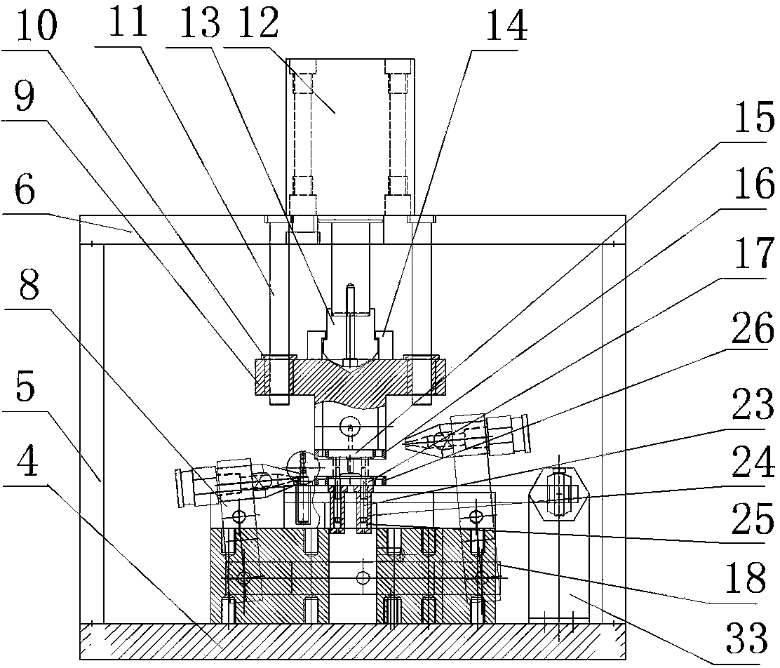
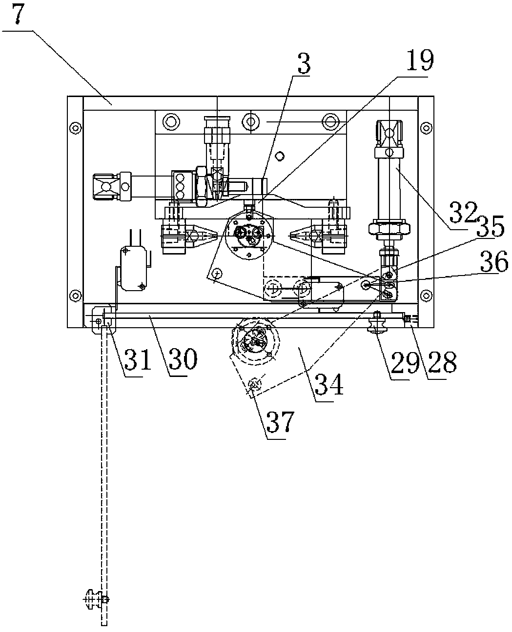
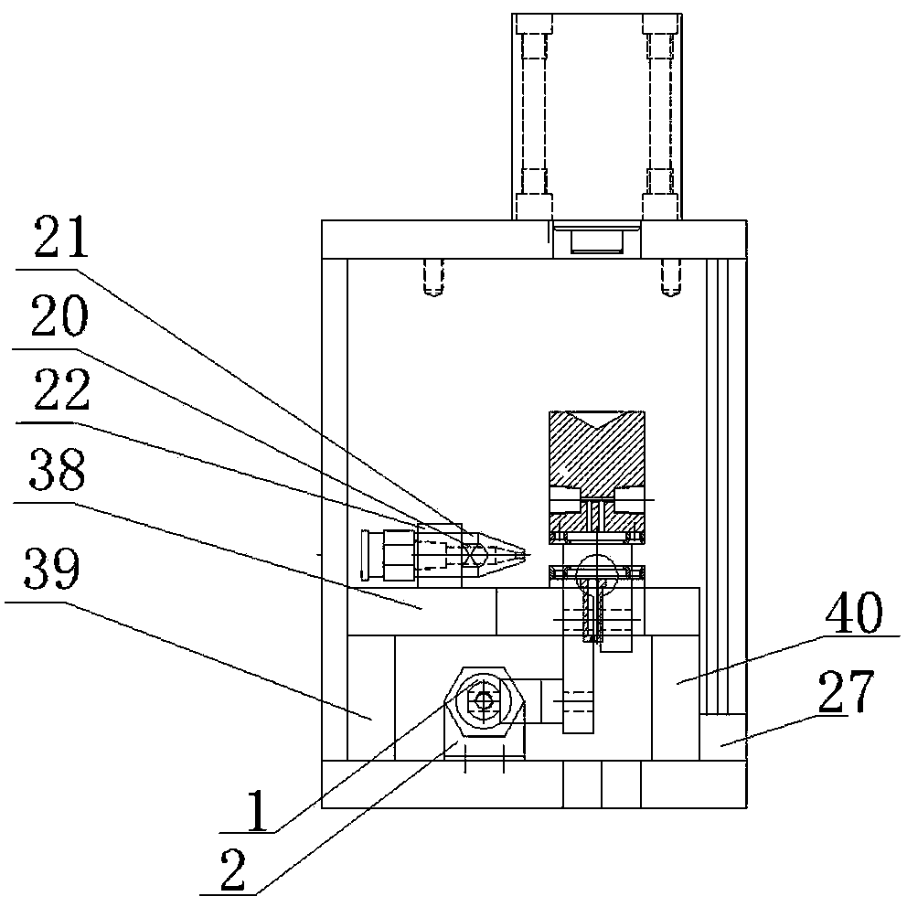
[0030] Such as Figure 1-3 As shown, a blowing device for a control valve includes a casing, a supporting part arranged in the casing, a clamping part, a blowing part and a pressing part,

[0031] The clamping part includes an indexing plate 34, on which a valve body positioning pin 23 and a valve body positioning sleeve 24 for clamping the valve body are arranged, and a spring 25 is installed below the valve body positioning pin 23. , the spring 25 is installed in the valve body positioning sleeve 24, and the positioning plate 34 is also provided with a valve core positioning sleeve 37 for clamping the valve core;

[0032] Described pressing part comprises press seat 9 and cylinder 12, and described cylinder 12 below is equipped with spherical head 13, and described press seat 9 ...

Login to view more

PUM

No PUM Login to view more

Abstract

The invention discloses a control valve air blowing device. The control valve air blowing device comprises an outer shell, a supporting part, a clamping part, an air blowing part and a pressing part, wherein the supporting part, the clamping part, the air blowing part and the pressing part are arranged inside the outer shell. The clamping part comprises a rotation plate, wherein the rotation plate is provided with a valve body positioning pin used for clamping a valve body and a valve body positioning sleeve, a spring is installed under the valve body positioning pin and is installed in the valve body positioning sleeve, and the rotation plate is further provided with a valve element positioning sleeve used for clamping a valve element. The air blowing part comprises a plurality of spraying nozzles, a plurality of air pipe connectors used for being connected with an air pump and the spraying nozzles, and a plurality of spraying nozzle fixing clamps used for fixing the spraying nozzles, wherein the positions of air blowing ports of the spraying nozzles correspond to the positions of workpieces clamped on the rotation plate. The control valve air blowing device is high in automatic degree, thereby being high in air blowing efficiency. The air is blown to the end surfaces, outer circles and inner cavities of the workpieces in place, the blowing cleaning effect is good, and the control valve air blowing device is more convenient, more rapid and safer to use.

Description

technical field [0001] The invention relates to a control valve cleaning device, in particular to a control valve blowing device. Background technique [0002] After the processing and cleaning of the control valve, there is also a blowing process. At present, the blowing of the control valve is generally carried out with compressed gas, while the ordinary blowing device generally only carries a single nozzle, and manual operation is required during the blowing process. Not only the blowing efficiency is low, but also the blowing angle is single, which makes the blowing not uniform, and it is difficult to blow the end face and outer circle of the workpiece in place, especially the inner hole of the workpiece is more difficult. Contents of the invention [0003] In order to solve the defects and deficiencies of the above-mentioned prior art, the present invention provides a control valve blowing device with high blowing efficiency, more effective blowing on the end face, ou...

Claims

Login to view more

Application Information

Patent Timeline
no application Login to view more
Patent Type & Authority Applications(China)
IPC IPC(8): B08B5/02B08B13/00
CPCB08B5/02
Inventor 郭苗成杨成贤
Owner HANGZHOU MEIBAH PRECISION MACHINERY
Who we serve
  • R&D Engineer
  • R&D Manager
  • IP Professional
Why Eureka
  • Industry Leading Data Capabilities
  • Powerful AI technology
  • Patent DNA Extraction
Social media
Try Eureka
PatSnap group products